Universal serial RS232/RS422/RS485 to multimode optic fiber media converter (4 ST type connectors )

NOTE : RD300-OFR has reached the end of its life cycle (to know more about its different deadlines click here).
Your sales representative is at your disposal for any questions.
Using fiber optic enables to use a higher communication bandwidth while offering a total immunity against EMI/RFI interferences and an increased security as well.
The optical fibre still offers other advantages : use without risk in an explosive environment, no EMC emission, no ground loops, immunity against lightning and high voltage environments, they are finally lighter, less cumbersome, inert and corrosion resistant …
Plug & Play: RD300 features a self configuration mechanism based on a CPLD component that frees you from the tiresome operation which consists in the serial parameters setup, product is “Plug & Play”.
RD300 features in standard a built-in system to control the fiber integrity, it reports automatically any failure with an error LED and also setups a relay contact (MOSFET) to activate any external safety device.
Its small size, design features and its great adaptability make the RD300 a really universal product capable to satisfy to major needs of the industry.
|
Conversion |
Serial RS232/RS422/RS485 to multimode fiber optic, RS485 mode self line turnaround
|
||
|
Serial speed |
2Mbps for RS422/RS485 mode, 1Mbps for RS232 mode
|
||
|
Distance |
5000m with a 100/140 µm fiber type at 25°C
|
||
|
Serial protocols |
The device supports any kind of communication protocols (Modbus, Unitelway, Profibus, DH+ and any ASCII or binary serial protocols …)
|
||
|
Configuration |
Serial link parameters auto configuration, no switches. Line polarization, termination and selection between RS232/RS422/RS485 modes are configurable by mini-switches.
|
||
|
Serial connectors |
Pluggable screw-in terminal, TxD & RxD signal for RS232 mode, TxA, RxA, TxB, RxB for RS422 mode, TRxA & TRxB for RS485 mode
|
||
|
Optic fiber |
50/125 µm, 62.5/125 µm, 100/140 µm, 820 nm wave length, selectable ON/OFF state of the fiber light at the idle state.
|
||
|
Power budget |
22.4 dB, 5 dB & 11 dB attenuator for short distance communication
|
||
|
Fiber connectors |
4 ST connectors
|
||
|
Network topologies |
Point to point, ring, single-master & dual-master, redundant fiber ring, dual ring & dual master, dual point to point, star
|
||
|
Signaling |
2 LEDs Tx/Rx for copper 2 LEDs Tx/Rx for fiber optic n°1 2 LEDs Tx/Rx for fiber optic n°2 1 LED for fiber n°1 breakdown 1 LED for fiber n°2 breakdown 1 LED for power
|
||
|
Fan-out |
31 RS485 interfaces, 10 RS422 interfaces
|
||
|
Input load |
Input load 1/8 UL in RS485 mode
|
||
|
EMI/RFI protection |
Built-in continuous line surge protection, ESD protection (15 KVeff), HF filtering
|
||
|
Isolation |
Infinite galvanic isolation through the optic fiber
|
||
|
CEM |
NF EN 55022 emission, NF EN 61000-6-2 immunity
|
||
|
Security |
Fiber breakdown self diagnostic, failure is reported on a LED and a relay contact (MOSFET) is activated.
|
||
|
Power supply |
+9VDC to +36VDC (pluggable screw-in terminal), 2.3W
|
||
|
Environment |
Temperature from -5°C to +65°C, storage -40°C to +80°C, relative humidity from 0 to 95% RH without condensation
|
||
|
Dimensions, weight |
107 mm (L) x 88 mm (l) x 25 mm (H), 260 g
|
This configuration enables to control a single equipment installed in a very polluted or distant area. The optical line is totally insensitive to EMI/RFI perturbations.

This topology enables to build a simple ring whereas the master equipment is installed in the middle.
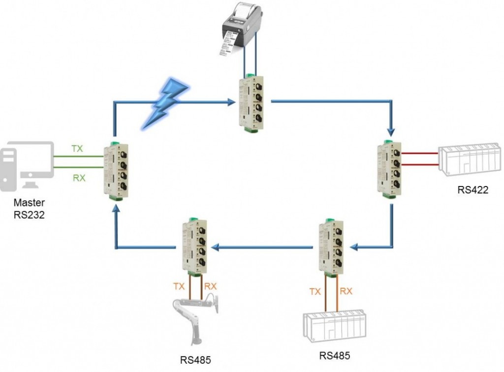
Each media converter device enables to connect to the network one or more slaves peripherals controlled by the master which governs exchanges using addressing sequences.
All the slaves equipments receive data transmitted by the master and answer are then received only by the master.
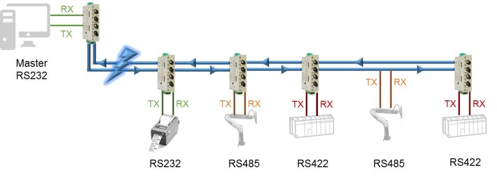
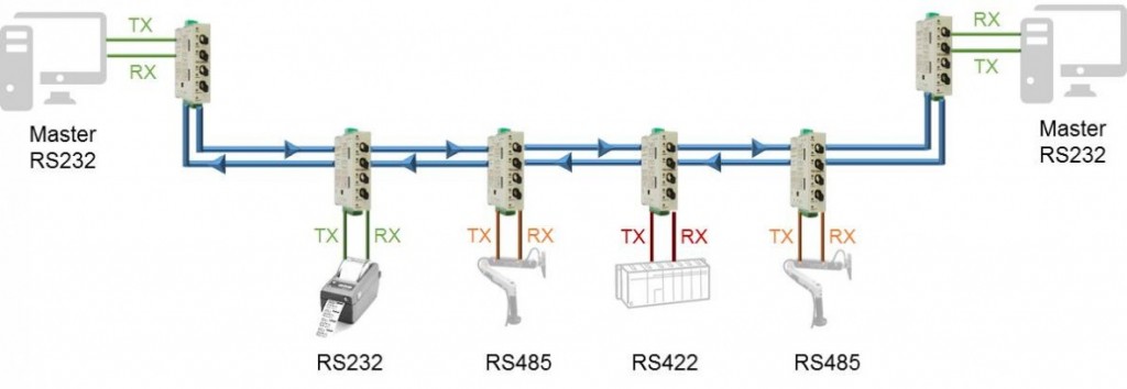
By using this configuration, data transmitted by the “A” master are received by all the slave equipments and by the “B” master (backup station) as well.
The answers from slaves are received by all the slaves and by masters “A” & “B” as well.
Such configuration brings security to the application as the “B” master warrants the system to work even in case of master “A” failure or fiber breakdown.
Both “A” & “B” masters can be a single equipment with two independant serial ports.
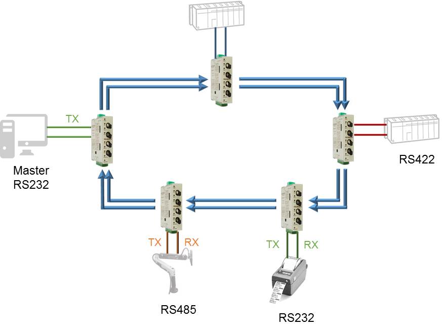
A single ring is used in this configuration but data are transmitted simultaneously on the two rings, this is a single master topology.
The master doesn’t retransmit the data he receive in order to avoid infinite data loop.
In case of fiber breakdown, the equipments will still continue to receive data on the only line.
This topology should be used when an equipment needs to answer to different masters located on distinct networks.
The RD300-OFR device can also be used as a simple repeater or as a fiber optic converter to be compatible with other equipments.
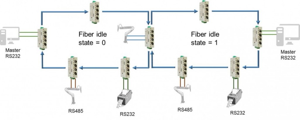
This topology should be used when EMI/RFI perturbations concern only a part of the whole installation.
Redundancy provides a double security for the sensitive link.
Moreover, any fiber failure is reported on a LED and a relay contact (MOSFET) in activated.

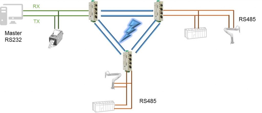
The device works as an RS485 network repeater and makes it possible also a star topology in a polluted environment.
Aucun document associé trouvé pour ce produit.

NOTE : RD300-OFR has reached the end of its life cycle (to know more about its different deadlines click here).
Your sales representative is at your disposal for any questions.
|
RD300-OFR |
Serial RS232/RS422/RS485 to multimode fiber optic media converter, multipoint & fault tolerant, +9VDC to +36VDC power supply, din rail mounting
|
